BLOG
HOME > BLOG >

3 measures to improve the return loss of RF Test Cables

Published by admin 2022-07-13

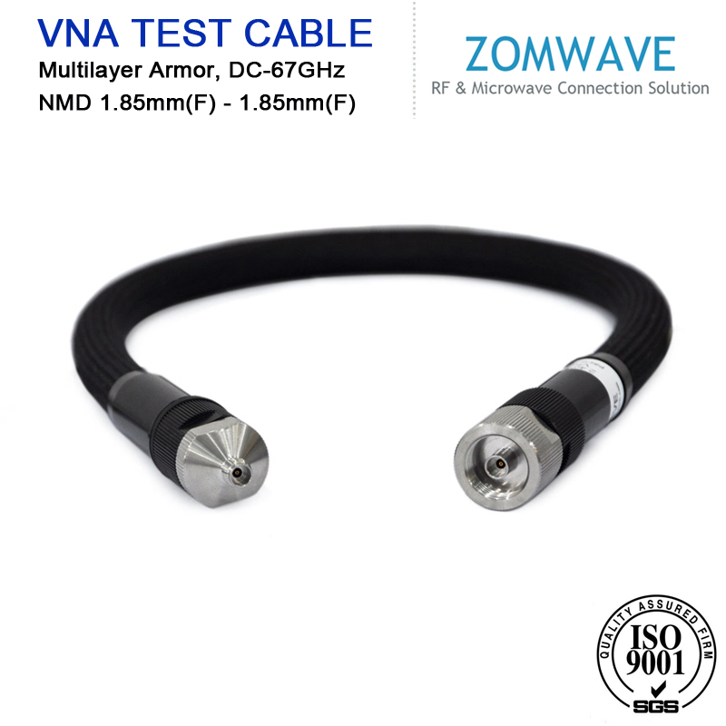
Return loss, also known as reflection loss. It is the reflection of the rf test cable link due to impedance mismatch, which is a reflection of the pair of lines themselves. The mismatch occurs mainly where the connector is located, but may also occur where the characteristic impedance changes in the rf test cable, so the quality of construction is the key to improving return loss. Return loss will introduce fluctuations in the signal, and the returned signal will be mistaken for the received signal by the duplexed Gigabit network and create confusion. Return loss is the ratio of the reflected wave power to the incident wave power at the transmission line port, expressed as an absolute value in logarithmic form in dB, and is generally a positive value.

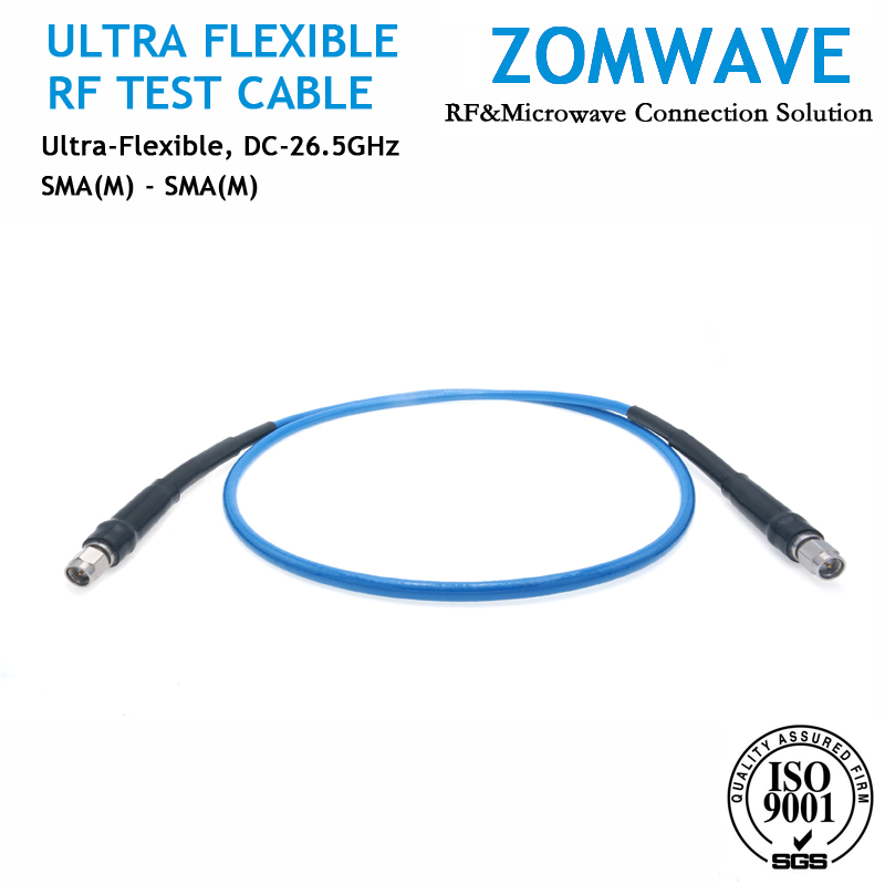
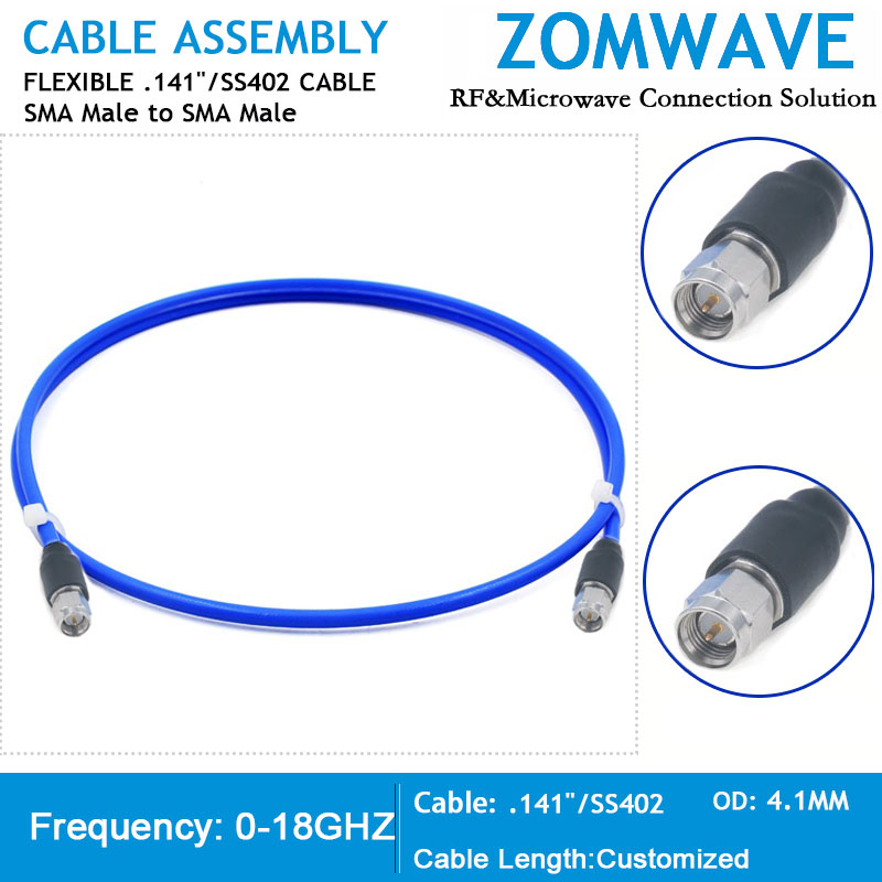
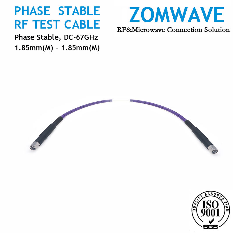
                                 rf test cable, rf test cables, ultra flexible cable
Return loss is an important indicator for rf test cable products. Return loss combines the effects of two reflections, including deviations from nominal impedance (e.g., 100 Ω) and structural effects, and is used to characterize the performance of the link or channel. It is caused by the inhomogeneity of the characteristic impedance over the length of the cable and, ultimately, by the inhomogeneity of the cable structure. Due to the reflections caused by the signal at different locations in rf test cable, the signal arriving at the receiving end corresponds to a multipath effect in the propagation of the wireless channel, which causes time spread and frequency selective fading of the signal, and time spread leads to pulse spreading, making the signal pulses at the receiving end overlapping and undecided. Multiple reflections of the signal in rf test cable also lead to attenuation of the signal power, affecting the signal-to-noise ratio at the receiving end and leading to an increase in the bit error rate, which also limits the transmission speed. In the process of producing digital cables, the return loss index of rf test cable is prone to failing.

                            
Measures to improve the return loss (RL) are the following three.

                            
1. Improve concentricity
In the insulation string production process, the diameter tolerance of the copper conductor is required to be within ±0.002mm, and the deviation of the insulation outer diameter is within ±0.01mm. Concentricity is above 96%, and the surface is smooth and round. Otherwise, the characteristic impedance of the single wire in the stranded rf test cable will have a large peak beyond the requirements of the index.


2. Composite technology
The use of a certain percentage of "pre-twisting" or "back-twisting" technology can eliminate the impact of insulation single-line eccentricity on the characteristic impedance, while reducing the concentricity of insulation single-line requirements. And the use of cross-type plastic skeleton, can maintain the stability of the rf test cable structure, so that the single line unevenly caused by the change in characteristic impedance becomes smooth, so that its near-end crosstalk and return loss in the high frequency performance is quite good.

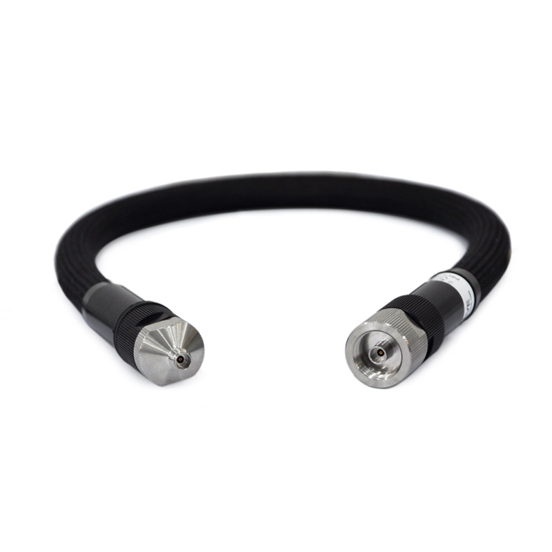
                                    rf test cable, rf test cables, vna test cable, vna cable assemblies    
It is well known that fluctuations in the center distance (S) of the two conductors in a wire pair cause fluctuations in the impedance of the wire pair. Due to the eccentricity of the insulated single line insulation layer is unavoidable, the line impedance changes show some degree of periodicity, in a number of local lengths remain unchanged, in the total length of a step-type sudden high and low fluctuations, the line consists of a number of sections of different impedance uneven segment length, these uneven segment length or long or short, when more than the cable frequency corresponding to the wavelength of 1/8, close to half wavelength, the impedance changes will By the traveling electromagnetic wave "detected" and lead to the reflection of electromagnetic waves, some of the reflections due to the same phase and superimposed together, resulting in impedance fluctuations, return loss decline and additional loss (attenuation - the peak on the frequency curve). As the frequency increases, the wavelength decreases, causing more uneven segment lengths to be reflected.

                            
Through the pair of "pre-twist" or "back-twist", so that the pair of conductors between the distance S to complete a cycle of change in the corresponding length contains a number of twisted pair pitch, but does not exceed the highest frequency of the cable corresponding to 1/8 wavelength, then the pair impedance in a pitch Also complete a cycle of rapid change in the size of its sinusoidal fluctuations, so that the total length of the pair impedance changes smoothly, reflections no longer occur, the uniformity of the pair impedance greatly improved. In addition, with the use of cross-shaped plastic skeleton to maintain the stability of the rf test cable structure, so that the change in characteristic impedance caused by the unevenness of a single line becomes smooth.


3. Use of adhesion wire pair technology
Adhesive pair technology process refers to the use of two extruders, a head co-extrusion, the same pair of two insulated core wire synchronous extrusion will be bonded together. Twisted pair of wire bonding, to ensure the stability of the twisted pair of wire structure, to maintain the stability of the center distance of the two wires (S) to improve the uniformity of the impedance of the pair, thereby improving the return loss index; can also avoid the insulation conductor by bending twisted conductor occurs after the core and affect the return loss index of rf test cable.

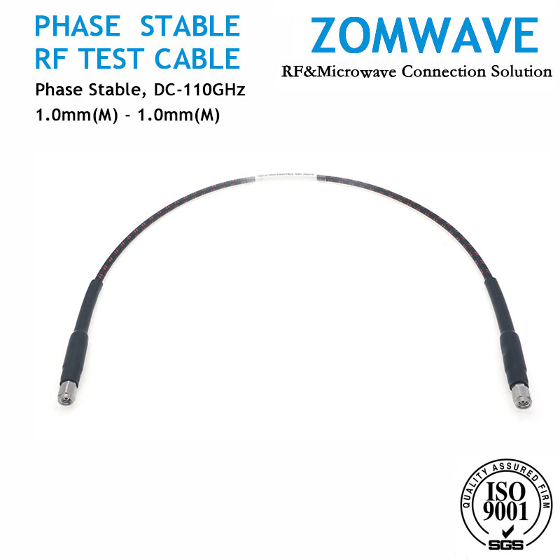
                          rf test cable, phase stable cable, phase matched cable

ZOMWAVE can deliver VNA Test Cable, Ultra Flexible Test Cable, Phase Stable Test Cable quickly with low price and high performance in 5 days. Click the blue words and learn more.

tel email whatsapp skype
Copyright © 2021 ZOMWAVE TECHNOLOGY CO., LTD
Technical Support: Magic Lamp